|
Introduction
Intrinsically
safe equipment is defined as "equipment and wiring which is incapable
of releasing sufficient electrical or thermal energy under normal
or abnormal conditions to cause ignition of a specific hazardous
atmospheric mixture in its most easily ignited concentration."
(ISA-RP12.6) This is achieved by limiting the amount of power
available to the electrical equipment in the hazardous area to
a level below that which will ignite the gases.
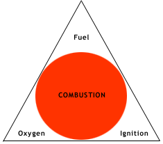
 In
order to have a fire or explosion, fuel, oxygen and a source of
ignition must be present. An intrinsically safe system assumes
the fuel and oxygen is present in the atmosphere, but the system
is designed so the electrical energy or thermal energy of a particular
instrument loop can never be great enough to cause ignition. In
order to have a fire or explosion, fuel, oxygen and a source of
ignition must be present. An intrinsically safe system assumes
the fuel and oxygen is present in the atmosphere, but the system
is designed so the electrical energy or thermal energy of a particular
instrument loop can never be great enough to cause ignition.
Traditionally,
protection from explosion in hazardous environments has been accomplished
by either using EXPLOSION PROOF apparatus which can contain an
explosion inside an enclosure, or PRESSURIZATION or purging which
isolates the explosive gas from the electrical equipment. Intrinsically
safe apparatus cannot replace these methods in all applications,
but where possible can provide significant cost savings in installation
and maintenance of the equipment in a Hazardous area. The basic
design of an intrinsic safety barrier uses Zener Diodes to limit
voltage, resistors to limit current and a fuse.
APPLICATIONS
A Hazardous Area may contain flammable gasses or vapors, combustible
dusts, or ignitable fibers or flyings. There are different systems
used in Europe or the United States to classify the type of hazard
and whether the Hazard is always present or only present in an
emergency condition such as a spill or failure of venting equipment.
(Refer to Pages Z-93, 94 in The OMEGA Complete Temperature Measurement
and Control Handbook and Encyclopedia® for U. S. Classifications).
In most cases the equipment is designed for the worst case, which
would be to assume the explosive atmosphere is always present
and the electrical or thermal energy is the lowest required to
cause a fire or explosion.

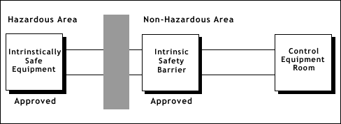
Most
applications require a signal to be sent out of or into the hazardous
area. The equipment mounted in the hazardous area must first be
approved for use in an intrinsically safe system. The barriers
designed to protect the system must be mounted outside of the
hazardous area in an area designated as Non-hazardous or Safe
in which the hazard is not and will not be present.
Equipment
which has been designed for and is available for use in hazardous
areas with intrinsically safe barriers includes:
•
4-20 mAdc Two Wire Transmitters
• Thermocouples
• RTDs
• Strain Gages
• Pressure, Flow, & Level Switches
• I/P Converters
• Solenoid Valves
• Proximity Switches
• Infrared Temperature Sensors
• Potentiometers
• LED Indicating Lights
• Magnetic Pickup Flowmeters
Most
of the apparatus that is mounted in the Hazardous area will have
to be approved and certified for use in the Hazardous area with
an approved barrier designed for use with that apparatus. Some
simple devices like thermocouples, RTDs, LEDs and contacts can
be used in the hazardous area without certification as long as
it is wired in conjunction with an approved barrier.
APPROVALS
Intrinsic safety equipment must have been tested and approved
by an independent agency to assure its safety. The customer should
specify the type of approval required for their particular application.
The most common Agencies involved are as follows:
COUNTRY
AGENCY
USA - FM, UL
CANADA - CSA
GREAT BRITIAN - BASEEFA
FRANCE - LCIE
GERMANY - PTB
ITALY - CESI
BELGIUM - INEX
NOTE:
approval by any of the above European Agencies constitutes a CENELEC
approval allowing the units to be considered approved in many
of the European countries.
Products
to be mounted in the hazardous area can be approved either under
the LOOP or ENTITY approval concept.
The
LOOP concept specifies the exact part number and products that
can be used in the loop. No deviation from the specified units
is allowed.
The
ENTITY concept specifies parameters which any approved intrinsic
safety barrier must meet. This allows the user to select barriers
from different approved manufacturers. Under entity approval two
items may be interconnected if the following conditions are met
(refer to chart below):
|
HAZARDOUS
AREA
|
|
NON-HAZARDOUS
(SAFE) AREA
|
| Intrinsically
Safe Approved Apparatus |
Must
be |
Intrinsically
Safe Barrier |
| Vmax |
less
than |
Voc |
| Imax |
less
than |
Isc |
| La |
greater
than |
Li
+ Lw |
| Ca |
greater
than |
Ci
+ Cw |
| Where: |
|
| Vmax
= |
Maximum
Open Circuit Voltage |
| Imax
= |
Maximum
Short Circuit Current |
| L
= |
Maximum
Unprotected Inductance |
| Ci
= |
Maximum
Unprotected Capacitance |
| Voc
= |
Maximum
Open Circuit Voltage (barrier) |
| Isc
= |
Maximum
Short Circuit Current (barrier) |
| La
= |
Maximum
Allowed Inductance (barrier) |
| Ca
= |
Maximum
Allowed Capacitance (barrier) |
| Lw
= |
Inductance
of interconnecting wiring |
| Cw
= |
Capacitance
of interconnecting wiring |
| In
all cases the intrinsically safe barriers and equipment MUST
be wired per an approved drawing. Capacitance and inductance
of the wiring and cables must be included in the loop evaluation. |
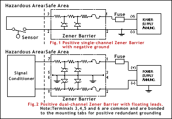
 In
all cases the intrinsically safe barriers and equipment MUST be
wired per an approved drawing. Capacitance and inductance of the
wiring and cables must be included in the loop evaluation. Fig.
1 Positive Single-Channel Zener Barrier With Negative Ground.Fig.
2 Positive Dual-Channel Zener Barrier With Floating Leads. Note:
Terminals 3, 4, 5 and 6 are Common and are Bonded to the Mounting
Tabs for Positive Redundant Grounding. In
all cases the intrinsically safe barriers and equipment MUST be
wired per an approved drawing. Capacitance and inductance of the
wiring and cables must be included in the loop evaluation. Fig.
1 Positive Single-Channel Zener Barrier With Negative Ground.Fig.
2 Positive Dual-Channel Zener Barrier With Floating Leads. Note:
Terminals 3, 4, 5 and 6 are Common and are Bonded to the Mounting
Tabs for Positive Redundant Grounding.
|


 In
order to have a fire or explosion, fuel, oxygen and a source of
ignition must be present. An intrinsically safe system assumes
the fuel and oxygen is present in the atmosphere, but the system
is designed so the electrical energy or thermal energy of a particular
instrument loop can never be great enough to cause ignition.
 In
all cases the intrinsically safe barriers and equipment MUST be
wired per an approved drawing. Capacitance and inductance of the
wiring and cables must be included in the loop evaluation. Fig.
1 Positive Single-Channel Zener Barrier With Negative Ground.Fig.
2 Positive Dual-Channel Zener Barrier With Floating Leads. Note:
Terminals 3, 4, 5 and 6 are Common and are Bonded to the Mounting
Tabs for Positive Redundant Grounding.