|
|
 |

The fundamental operating principles of force, acceleration, and torque instrumentation are closely allied to the piezoelectric and strain gage devices used to measure static and dynamic pressures discussed in earlier chapters. It is often the specifics of configuration and signal processing that determine the measurement output.
An accelerometer senses the motion of the surface on which it is mounted and produces an electrical output signal related to that motion. Acceleration is measured in feet per second squared, and the product of the acceleration and the measured mass yields the force. Torque is a twisting force, usually encountered on shafts, bars, pulleys, and similar rotational devices. It is defined as the product of the force and the radius over which it acts. It is expressed in units of weight times length, such as lb.-ft. and N-m.
 |
| Figure 6-1: Piezoelectric Sensor Element Designs
|
Force Sensors
The most common dynamic force and acceleration detector is the piezoelectric sensor (Figure 6-1). The word piezo is of Greek origin, and it means "to squeeze." This is quite appropriate, because a piezoelectric sensor produces a voltage when it is "squeezed" by a force that is proportional to the force applied. The fundamental difference between these devices and static force detection devices such as strain gages is that the electrical signal generated by the crystal decays rapidly after the application of force. This makes these devices unsuitable for the detection of static force.
The high impedance electrical signal generated by the piezoelectric crystal is converted (by an amplifier) to a low impedance signal suitable for such an instrument as a digital storage oscilloscope. Digital storage of the signal is required in order to allow analysis of the signal before it decays.
Depending on the application requirements, dynamic force can be measured as either compression, tensile, or torque force. Applications may include the measurement of spring or sliding friction forces, chain tensions, clutch release forces, or peel strengths of laminates, labels, and pull tabs.
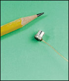 |
Tiny accelerometer is
useful for low-mass
laboratory applications.
|
A piezoelectric force sensor is almost as rigid as a comparably proportioned piece of solid steel. This stiffness and strength allows these sensors to be directly inserted into machines as part of their structure. Their rigidity provides them with a high natural frequency, and their corresponding rapid rise time makes them ideal for measuring such quick transient forces as those generated by metal-to-metal impacts and by high frequency vibrations. To ensure accurate measurement, the natural frequency of the sensing device must be substantially higher than the frequency to be measured. If the measured frequency approaches the natural frequency of the sensor, measurement errors will result.
 |
| Figure 6-2: Impact Flowmeter Application
|
Impact Flowmeters
The impact flowmeter is also a force sensor. It measures the flow rate of free flowing bulk solids at the discharge of a material chute. The chute directs the material flow so that it impinges on a sensing plate (Figure 6-2). The impact force exerted on the plate by the material is proportional to the flow rate.
The construction is such that the sensing plate is allowed to move only in the horizontal plane. The impact force is measured by sensing the horizontal deflection of the plate. This deflection is measured by a linear variable differential transformer (LVDT). The voltage output of the LVDT is converted to a pulse frequency modulated signal. This signal is transmitted as the flow signal to the control system.
Impact flowmeters can be used as alternatives to weighing systems to measure and control the flow of bulk solids to continuous processes as illustrated in Figure 6-2. Here, an impact flowmeter is placed below the material chute downstream of a variable speed screw feeder. The feed rate is set in tons per hour, and the control system regulates the speed of the screw feeder to attain the desired feed rate. The control system uses a PID algorithm to adjust the speed as needed to keep the flow constant. Impact flowmeters can measure the flow rate of some bulk materials at rates from 1 to 800 tons per hour and with repeatability and linearity within 1%.
|